Intro
[V2] Specification: EN, CN
Demo Videos: YouTube, bilibili
Linkedin: Link
Papers & Datasets: Link
Setup
Hardware Setup
Assemble the cable harness following this guide: Link to document
Input Power Requirement: 9–36 V, >25 W
Power Connector: 5.5 × 2.1 mm barrel jack (default)
Ethernet Connector: 100BASE‑T1 or RJ45 (via adapter)
Further details regarding the CAD file and cable harness are provided in the following sections.
Connect the power source to the device. The board will then begin its power‑on sequence, which typically takes approximately 10–20 seconds to complete.
Software Setup
SW Requirements for ROS driver: ROS 1 Noetic + Ubuntu 20.04 or ROS 2 (compatible distributions)
Default IP Address: 192.168.3.10
Further details regarding the software interface can be found in the following sections.
Open Settings in Linux and navigate to the Network tab.

If your machine has multiple network interfaces, you will see several devices listed—similar to the screenshot above. Locate the device that corresponds to the Ethernet connection used with the radar sample. In the example shown, a USB‑C adapter was used, so the device appears as “USB Ethernet.”
Click the gear icon next to the appropriate network device, then switch to the IPv4 tab.
Under IPv4 Method, select Manual.
In the Addresses section, add a new entry with the following values:
Address: 192.168.3.1
Netmask: 255.255.255.0
Leave the Gateway field empty. The window should now appear like this.
Click Apply to save the changes.

Changing IP address
With radar powered on and connected to a PC.
In a web browser, type in address http://192.168.3.10:3000
Then click on “Network configuration”
Then type the address and click “Apply”

Changing Installation Height [V2]
With radar powered on and connected to a PC.
In a web browser, type in address http://192.168.3.10:3000
Then click on “Installation Configuration”.
Then select the box “Flip points below ground” under “Pointcloud”.
Then type in “Installation height (meters)” and click “Apply”.
Power cycle the radar and the new height is set.
“Installation height (meters)” is the vertical distance from the center of the radar to the ground.

Changing Multi/Unicast Destination Address
The multi/unicast destination address can be configured in the “Installation Configuration” section.
For both multicast and unicast, the destination port must be entered in the ROS driver:
- [V2] GROUPPORT: altosRadarParse.cpp#L29 (ROS1) or altosRadarParse.cpp#L30 (ROS2)
Selecting Operating Mode
[V2] Altos radar supports different max-range mode, like 80m-320m, 40m-120m, 80m-500m, etc.
Take “80m-320m” mode as an example. In each frame of point cloud, the radar outputs 2 sub frames of data, one of 0-80m range (with higher range resolution) and another subframe with point cloud between 80m to 320m (with lower range resolution).
The operating mode can be selected at the drop down manual of “Profile” under “Installation configuration”.
The operating mode can be changed in real time with the radar stopping for seconds.

Config with Command Line
In the web GUI, clicking “CURL” besides the button “APPLY” can generate the command line. Change the values in the command line by need.
Software Interface
The sensor sends out point clouds as UDP packet via Ethernet.
[V2] C++ Header for UDP: pointCloud.h
[V2] Interface Control Document: Link to document
ROS Driver
[V2] ROS1 noetic: Link to repo
[V2] ROS2: Link to repo
UDP data is converted into standard ros msg format: sensor_msgs/PointCloud2.
The data fields of pcl::PointXYZHSV:
- x, y, z: coordinates in [m]. The origin point is the center of radar radome. The coordinate system is right-handed: x-forward, y-left and z-up.
- h: measured relative doppler velocity in [m/s].
- s: estimated RCS in [square meter] based on SNR, distance and angle. RCS, Radar cross section indicates the reflection strength from an object and can be used in a certain way for detection confidence or reliability. The value is on a linear scale [sm], not logarithmic [dBsm].
- v: moving status, [-1,0,1] = [moving towards, standing, moving away]. We do not use any external data, e.g. from IMU, but only the radar point cloud to estimate the ego velocity and to determine the point moving status.
Parser for Non-ROS User [V2]
Link to repo
This is only a C++ parser of UDP data for radar point cloud. Storage, visualization, playback or other functions are not realized.
PTP and Timestamps
PTP manual: Link to document
The example provided in the manual matches the default settings in the configuration page. Please do not change the default settings.
ROS timestamps
The actual capturing / measurement time of each frame is sent out in the UDP packets, see pointCloud.h#L24
The default header.stamp uses ros::Time::now() in the PC, since it is easy for visualization in rviz without correct PTP time, see altosRadarParse.cpp#L223
After setting up PTP, you can decode the timestamp from UDP packets and save it into header.stamp.
The timestamp is generated at the midpoint of the modulation.
FPS limit
The FPS limit is configurable in the “Installation configuration” section.
The maximum supported FPS is 15Hz.
Second offset-based triggering
Triggering with a configurable offset from the UTC second can be enabled and adjusted in the “Installation configuration” section. To use the second offset, ![]() the FPS limit must be activated and set to an integer value; otherwise, some triggers may be skipped.
the FPS limit must be activated and set to an integer value; otherwise, some triggers may be skipped.
Each trigger event generates a number of frames equal to the configured FPS limit. The trigger time—or equivalently, the timestamp of the first frame—is aligned with the integer second boundary of the reference time, shifted by the specified second offset.
Trigger timing typically exhibits jitter in the range of tens of microseconds (μs).

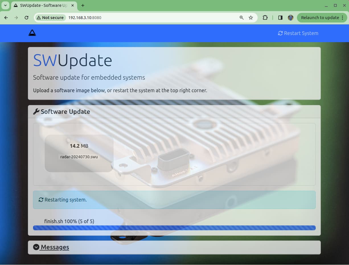
Firmware Update
With radar powered on and connected to a PC.
In a web browser, type in address http://192.168.3.10:8080
Then drag the *.SWU files that Altos Radar provided to the software update box on the webpage.

After a minute or so, if it succeeded there will be a message and the radar will restart.
Alternatively, once the message “SWUPDATE successful !” appeared, it’s OK to power cycle the radar manually.
Update with Command Line
curl --form file='@altos-v2-rootfs-xxxx.swu' http://192.168.3.10:8080/upload
Replace the swu file name and IP address if changed.
Wait a few minutes after the curl command completes and the radar will automatically reboot
CAD File
[V2] Link to step file
Cable Harness
Altos radar uses a 2+6 pin radar connector, including DC voltage supply and 100 base-T1.
Connector Pin Assignment: Link to document

Errata
Link to document
Please ask your contact at Altos Radar for password.
Interference Avoidance
[V2] We provide a dedicated SW for interference avoidance between 2-4 Altos V2 radars by using different operation frequencies.
Please ask your contact at Altos Radar for password.
Support
If you require further assistance, please contact our team directly at support@altosradar.com. We will respond as soon as possible.